| AN7118S - Low
Voltage Dual 35mW Audio Power Amplifier Circuits (BTL 300mW)
Overview
-
The AN7118S is the ICs designed for power
amplifier of low voltage operated compact radio and stereo tape recorder.
Stereo operation is enabled due to incorporating two amplifiers on one
chip. Miniaturization of cassette and high integration is realized due
to SOP package.
Features
-
Low voltage operation : VCC = 1.8V to 4.5V
-
Reduced voltage operation is available.
-
Low pop noise when supply voltage is switched
ON and OFF
-
Stereo drive of 4½ (speaker) to 32½
(headphone) load is possible.
Pin Description:
| Pin No. |
Pin Name |
Pin No. |
Pin Name |
|
1
|
GND (Output) |
10
|
GND (Input) |
|
2
|
Output Ch.1 |
11
|
Input Ch.2 |
|
3
|
NC |
12
|
N.F.B |
|
4
|
Bootstrap |
13
|
Phase Compensation |
|
5
|
Phase Compensation |
14
|
Phase Compensation |
|
6
|
Phase Compensation |
15
|
Bootstrap |
|
7
|
N.F.B |
16
|
NC |
|
8
|
Input Ch.1 |
17
|
Output Ch.2 |
|
9
|
Vcc |
18
|
Ripple Filter |
|

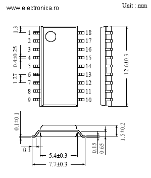
18-Lead SOP Package (SOP018-P-0300)
|
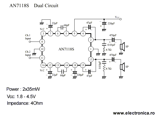
Application Circuit from Panasonic Datasheet:

Supplementary Explanation of IC Characteristics
-
Not necessary for input coupling
capacitor. Input electric potential is about 0 bias, using PNP Tr for input
stage.
-
One chip dual amp. (Stereo operation)
-
Battery operation is possible
at 1.8V to 4.5V
-
Decreased voltage operation
is available, and suitable for a long battery operation.
-
Load impedance can be driven
from 4½, which makes it possible to use for both speaker and headphone.
-
Small shock noise at power ON
and OFF.
Datasheet
for AN7118S  |

